
 Compare
 Sign in
Pneumatic Robot Tool Changers: Check Load, Air and Connections
Read two paired couplings without confusing their ratings with robot capacity.
RobotLineup Editorial · · Updated
Identify both halves of the coupling
A robot tool changer connects a robot-side part to a tool-side part. A quotation therefore needs to identify the pair and its configuration, rather than just a photograph or a family name. The BRQC-RA08 drawing labels the robot-side part RA08-R and the tool-side part RA08-T. The RA10 drawing uses the corresponding RA10-R and RA10-T designations. These examples are accessories for a robot installation, not industrial robot arms. This guide compares the supplier documents for those two couplings; it does not report an equipment test.
Read rated load and component mass as separate values
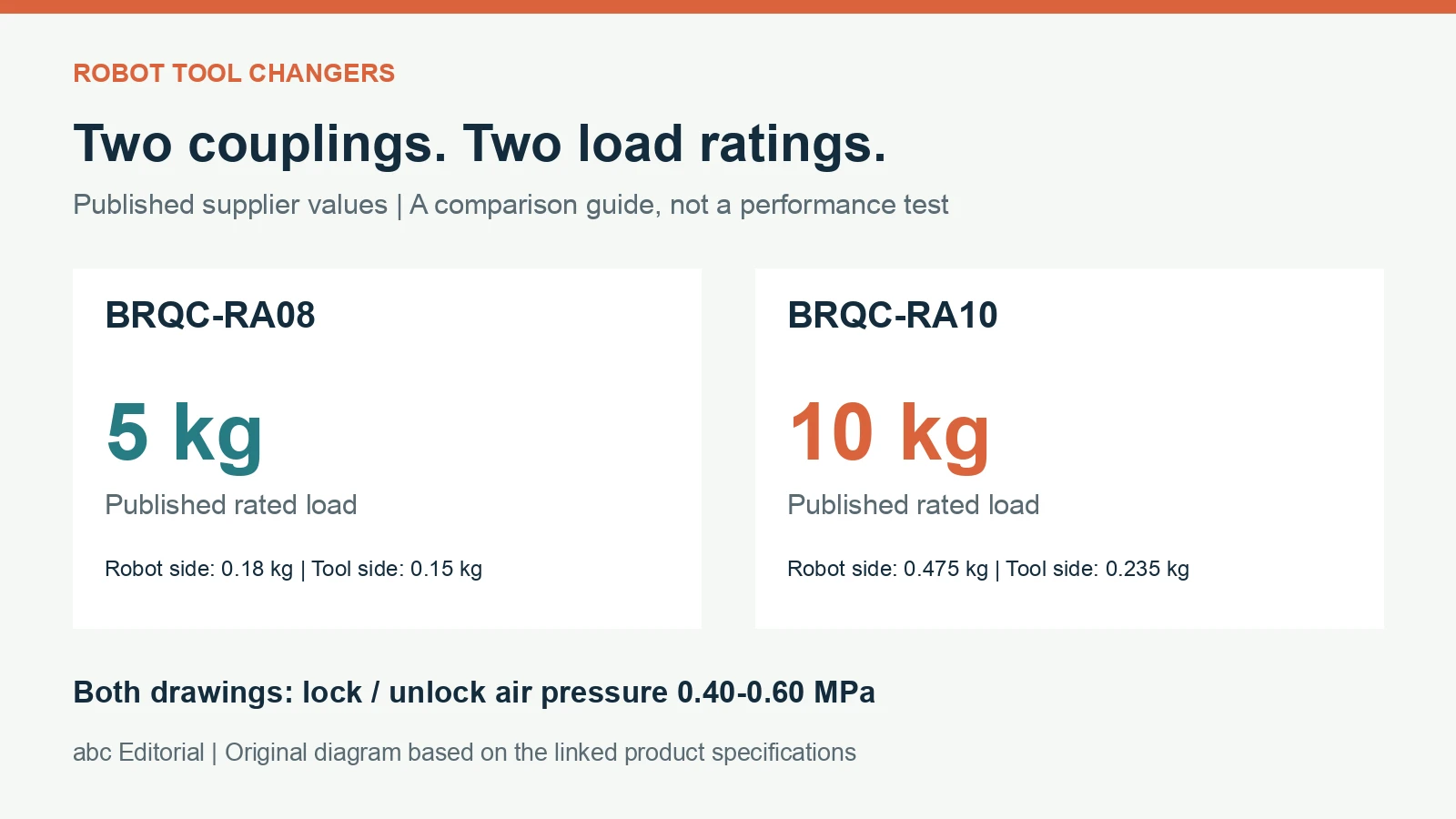
The RA08 drawing gives a rated load of 5 kg, with a 0.18 kg robot-side component and a 0.15 kg tool-side component. The RA10 drawing gives a 10 kg rated load, with component masses of 0.475 kg and 0.235 kg respectively. The coupling rating is not the payload rating of the robot to which it will be fitted. Provide the intended robot, tool and workpiece details and ask the supplier to confirm what the coupling rating includes. A catalog load figure alone does not establish the suitability of the complete moving assembly.
Confirm the pneumatic supply and change sequence
Both drawings state a locking and unlocking air-pressure range of 0.40–0.60 MPa and list six air circuits. Keep the pressure requirement separate from the number of circuits: one describes a supply condition, while the other describes connections in the published configuration. Ask how the offered unit is connected and controlled, how coupling state is detected and what checks are required before motion. The documents captured for this comparison do not establish the complete cell control sequence or an installation-specific safety assessment.
Check the electrical configuration in the quotation
The RA08 table lists nine electrical signals. The RA10 table uses the notation 9×2. Both sheets say that D-SUB connectors require a separate quotation. Do not assume that every connector illustrated is included in the base supply or that a signal count describes a particular fieldbus or electrical rating. Send the intended signal list and request the pin assignment, connector details, included accessories and electrical limits for the offered configuration.
Use the exact mounting drawing
The two drawings show different mounting layouts. A higher load rating does not establish that the larger-rated coupling will replace the other unit without changes. Compare the robot flange, tool-side mounting, available clearance and connector access using the current drawing supplied for the ordered pair. RA08 also notes that mounting holes can be customized to customer requirements. If customization is proposed, obtain the revised drawing rather than relying on the standard catalog image.
Prepare a focused sourcing brief
Identify the exact coupling model and both mating halves. Include the proposed robot, tool description, tool and workpiece masses, mounting drawings, pneumatic supply and required air and electrical connections. Ask the supplier to identify any options and explain the scope of its published rating. The linked directory records retain the supplier values without asserting interchangeability, availability or independently tested performance. This guide was prepared by RobotLineup Editorial with AI assistance from official drawings; software editing and approval roles do not constitute a separate human engineering review.
Buyer decision notes
Build two loading records and one service schedule
Tool-changer selection becomes clearer when the coupling and host robot are reviewed separately. The original guide records the published RA08 and RA10 facts; this worksheet turns them into questions about the exact mounted assembly. Do not use another brand’s moment limit or locking behaviour to fill a BRQC data gap.
Prepared by RobotLineup Editorial · Analysis updated . Platform analysis, not an independent equipment test.
Compare proposals on the same basis
Ask each bidder to answer these items against the same drawings, parts and operating sequence. An unanswered item is a comparison gap, not a passed requirement.
| Decision | Evidence to request | Avoid this assumption |
|---|---|---|
| Coupling loading | Removable-tool geometry and the supplier’s rated-load boundary and moment limits. | The kg figure alone permits any long or offset tool. |
| Host robot loading | Both coupling halves, adapters, tool, services and workpiece in the robot’s loading review. | Only the removable gripper belongs in the robot mass schedule. |
| Utility package | Required pneumatic circuits and separately itemised electrical and status connections. | A circuit count defines flow or optional electrical hardware. |
| Operating sequence | Documented docking, coupling confirmation and application response to incomplete changes. | Pneumatic actuation establishes loss-of-pressure retention. |
Record unknowns next to the proposed configuration
For each candidate, retain the actual mounting drawing and tool mass breakdown. Keep unresolved moment capacity, operating-status signals and air-loss behaviour in the comparison table instead of hiding them in a general caveat. A larger rated load does not close those gaps.
Ask for a quote that identifies each coupling half, service module and adapter. If one item changes, update both the coupling-loading and robot-loading records. The same assembly can be inside one stated mass boundary while requiring review under another.
Worked sourcing brief
Illustrative procurement exercise. Assumptions below are invented for explanation; this is not a customer case, trial result or quotation.
Assume two proposals show the same removable tool but one adds a heavier adapter and an electrical module. Their coupling headline figures alone do not describe the same host-robot load. List the actual mounted items and request each supplier’s limits and rating boundary. The exercise does not calculate an allowable dynamic moment or approve either proposal.
What to record before acceptance
Agree the test method, responsibilities and pass conditions before ordering. The items below are records to request, not a completed validation.
- Save both loading records with the confirmed geometry and rating definitions.
- Keep an itemised utility and connector schedule matching the final quotation.
- Retain model-specific operating documentation and the integrator’s agreed acceptance record.
Common buyer questions
Can I calculate an allowable moment from rated payload alone?
No. Request the manufacturer’s applicable moment limits and loading conditions.
Is a shared service specification proof of interchangeability?
No. Confirm mating parts, mounting and modules for the exact selected assembly.